When you both figure this stuff out, please start a topic on beam file tweaking for automation cars. I think it would help everyone! 

3 Likes
Ok that’ll be my mission this week. It always bothered me that my esc settings were appropriate but the idiot proofing didn’t extend to wild applications of throttle without just cutting the whole thing out. I want to create a seamless experience.
EDIT: First attempt. Kept the turbo section in the engine.jbeam file. Created new references in the electronics.jbeam file. Did diddlysquat as the “mainengine” reference in the engine file overrode everything so it all defaulted to that section and so I only had one turbo setting.
Second attempt: deleted the turbo section of the engine.jbeam file. Put separate entries for turbochargers in the electronics.jbeam file nested into each ESC mode. Now I have no turbocharger as there is nothing occupying the turbo slot in the engine file.
I guess I don’t really understand how this part:
"mainEngine": { //turbocharger name "turbocharger":"turbocharger", //Just tells the engine to look for the turbocharger section of this name
works but I’m not entirely certain that fixing this path will still lead to the files parsing correctly as I don’t know how I would create a file that has all of that in it. I can’t see any mention of a relevant command in the wiki, either.
Maybe I’ll ask on the beam forums.
4 Likes
While we’re talking about .car files, is there a way to modify the engine note, specifically to make it more raspy? I would make a thread, but doubt I could find much help.
You can change the sound bank of the turbo and supercharger effects as Beam has some pre-specified ones, but the whole sound conversion issue on export is a completely different beast… just ask Daffy it’s been grinding his gears for years 
3 Likes
Damn… thanks for the info tho 
*Cries in M4 replica
Now that the She-Devil has been sold (for about twice as much as I expected), I can make this final post which rehashes all the content in one place, and that will finally be it for this model, and on to the next because I could milk it more with art and shit I think it’s more than time to move on because it’s hard to keep with the cool kids if you just do the same thing over and over again. Also I need to stop drawing the succubus giantess.

The original temptress, the irresistible demoness. Can you quench the fires of her lust, or will your soul be consumed like all before you?

only blocked in 246 countries lol
This video link will actually work
Following a highly successful year for their motorsport division, Team Ninja Horse (in particular their partnership with Znopresk Automobil to dominate the AMWEC), Gryphon Gear merged with fellow small performance outfits Dark Shine Designs and a large portion of Soltra in 2016. Thus they were able to expand the scale and the scope of their operations. But this was a big gamble, as it depended on them being able to capture a share of a highly competitive market quite different to their usual ultra-niche investors. The challenge was to stay true to their ultra-performance roots, while making something new, and something more accessible, for turnover an order of magnitude higher than any of their other projects.
Prior to this, they had flirted with the idea of having a crack at the “slightly more reasonably priced” supercar as opposed to their private race cars and ludicrous hypercars, but beyond a number of limited run projects with larger manufacturers, they lacked the capital to go it alone. But with the booming interest in high performance going unabated, 2017 was to be their time. The proposed price would be around 350k, and, in line with their competitors, the aim was to produce between 350-400 units. Single trim, you get what you get and if you want extra it’d be up for negotiation.

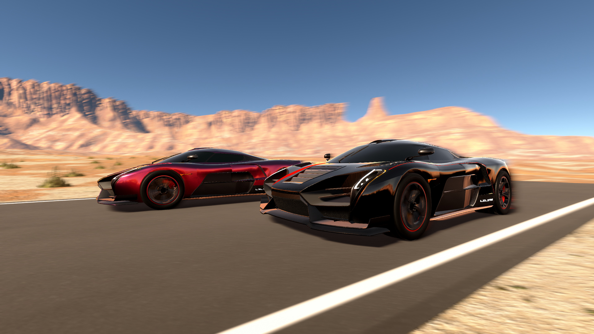
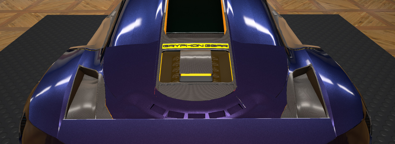
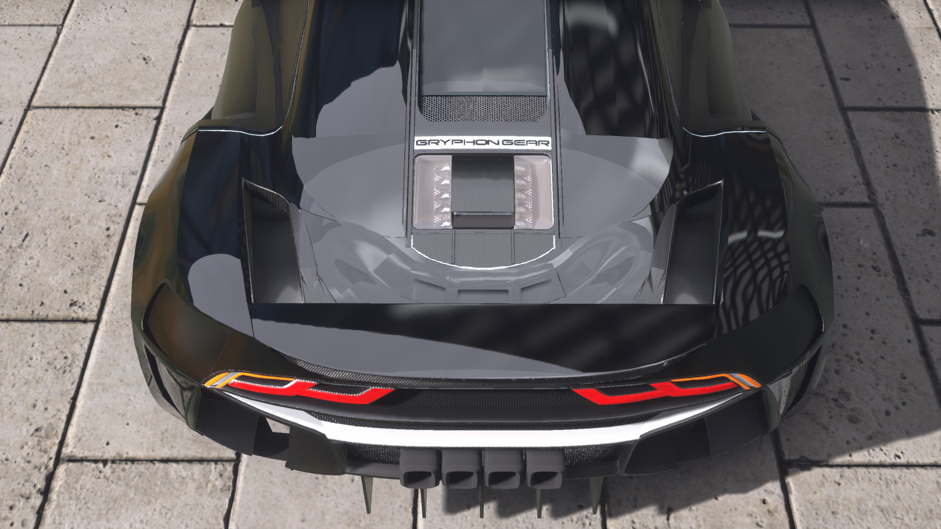
Lilith was the first GG factory car that was truly built to be lived with more than flung around by a professional race driver. Nonetheless it retained the GG philosophy in every aspect of being lighter and sharper and doing everything for the sake of speed, including the integrated torque distribution system in development since the Mercury project, and 4 way active aero, but eschewing the active spring suspension, surround sound systems and luxury seats common to its competitors. It was firmly pegged on the more committed end of the spectrum, yet hundreds of hours were spent ensuring that the ride had road manners as well as visceral racing feel. The V8 may have felt a relatively “pedestrian” choice to some but the 10000rpm redline was anything but. Boosted by GG’s “go fastest” reputation, the pre-order list filled up faster again. And once cars were delivered, interest surged yet again once it became clear that the quest to create something that lived up to its iconography had been a success: Lilith was far more potent than a regular mortal could handle yet far too tempting not to try. Evidence of its appeal came with the record sale of a model with the unique “She Devil” livery with factory decals, the face of their marketing campaign, for an astronomical 2.665M.

This placed GG in a strong, yet also delicate position. Their fanbase was created off a defiant celebration of the ICE. Their motorsport activities heavily leaned on the same. Yet within the space of a decade they had gone from brute force and a sledgehammer to embracing finesse and innovations of the future. Such wisdom indicated the decline of the ICE was upon them, and they had cannily responded by making Lilith a truly economical performance machine (at 6.2L/100km!), but even this would soon not be enough. A time would come when they would have to make the commitment to switch energy sources, making this even more so one of the last hurrahs for the screaming, flame spitting octane burning engines of yore.
Fact Sheet
Overview
| Manufacturer | Gryphon Gear |
| Production | 2017-present |
| Assembly | Donnybrook, Victoria, Australia |
| Designer | Stroppy McHorseguy |
Body and chassis
| Class | Sports car |
| Body Style | 2-door coupé |
| Layout | Rear mid-engine, rear-wheel drive |
| Platform | Carbon-aluminium composite monocoque |
| Doors | Dihedral |
Powertrain
| Engine | 4400cc VVT-L bi-turbo V8 |
| Power | 810bhp @ 9000rpm |
| Transmission | 7 speed DCT w/ E-LSD |
Dimensions
| Wheelbase | 2.34m |
| Length | 3.96m |
| Width | 2.01m |
| Height | 1.10m |
| Weight (dry) | 1254kg |
Performance on factory Trofeo tyres
| Top speed | 368km/h |
| 0-100km/h | 2.50s |
| 1/4 mile | 9.43s |
| 1km | 16.86s |
| 20m skidpan | 1.29g |
| 250m skidpan | 1.42g |

Someone pointed out that the succubus must have been like nearly seven foot tall. Well, I’m going to own that and say yeah sure, the company hired a seven foot tall model for the photo shoot lol. Bite me.
30 Likes
Still waiting on that jbeam tweaking guide ;-;
It’s worth noting that I never wrote a .jbeam tweaking guide because I’m still learning a lot of things about how to adjust .jbeam files. And also I’ve been too busy at work, which you won’t notice because all that means is that I make an average of 2 good cars a year.
But as of late, secret’s out, I’m remaking another GG car.
2015 Mercury
Back in, well, 2015, when the game was still in Kee engine, I thought I’d finally give my hand at properly flogging the one mid-engined body the game had at the time, which meant +15 tech spam everywhere, a stupid big engine that needed its own oil refinery, and enough fixtures to crash the game every time you clicked on the car. This was also back in the day when 8 cylinders was the most we had. The ensuing result was… well I’ll quote myself.
As if I didn’t spend most of this company thread making shit like that anyway. But Mercury was special because I wanted it to be the first car to break a number of benchmarks in the game at the time, including a 2hp:1kg ratio.
Later on, I decided I’d see if I can make it “street legal” and send it to 500km/h.
Suffice to say the design was awkward because I was trying to force the body to do things it really didn’t want to do. I was also forcing the engineering to do things the game didn’t want me to do so that Mercury ended up horribly unreliable and undriveable so I always wrote it into the lore that, well, the technical achievements were a Pyrrhic victory at best.
Fast forward 4 years and the game’s changed a lot. So I figured I’d take another look at the car. Turns out that the only body which actually suits my original aims is the same, only now the morphs behave differently and the seams are horrible and indelible which makes it hard for someone like me to work.
Anyway, as is customary I’ve reached about halfway through the first draft so have some mock-ups. The colours are as always only chosen so I can see what I’m doing, but who knows what it’ll be when I finish.

I can’t design the headlights for shit, FML

God damn changing the shape of the windows and roof-line is torture on this body

so tempted to just give this Regera tail lights and be done with it
Something’s just not sitting right with me, so as usual I guess one could expect some pretty drastic changes down the line. What won’t change is that it will have over 2000hp and hit 500km/h fair dinkum and pack a shit ton of downforce so it’ll corner like the clappers too.
edit: here’s an idea… not sure if I’ll keep it…
28 Likes
Impressive stuff, making that body look low enough to not be ridiculous. Good colour combo, and man. That door. Keep it up
butts

I could really do with some help with the colour scheme actually. Suggestions?

More progress to follow when I work out how to do the headlights and also finish the side panels.
Also could I ask the creator of the nega tape mod a massive favour and suggest that they redo the mesh of their fixtures to make it an even grid instead of radial vertices? Coz they’re fantastic for masking but they also stamp absolutely horrendously because I imagine they were only intended for use to make things blank, but other options make a huge difference.
32 Likes
I remember when I was back in 9th grade, during the survival swimming portion of gym class, I scrolled through this photo on my phone. I remember thinking to myself, “holy bejesus what the fuck” (in the kindest way!)

Please do something that’s as garish as this lime green.
Maybe like a Mazda Polymetal Grey with green accenting.
16 Likes
I think that dark blue with gold accents might work quite well, I’ve also done a lighter, icy blue with white highlights. Bright blue and lime green for my electric stuff. Yellow and black (carbon maybe) always looks good, just depends how messy it’s going to get to cover things up. I’m really liking it so far though.
So, uh, I got distracted by CSR116 and ended up farting around with Kelpie in Beam…
21 Likes
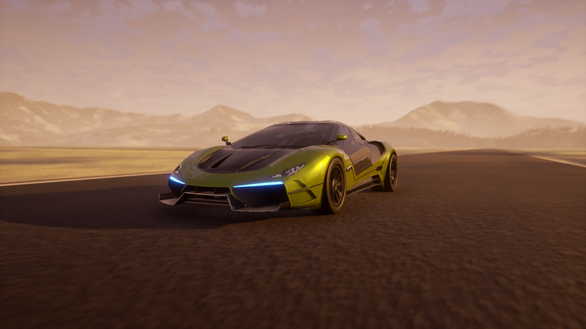
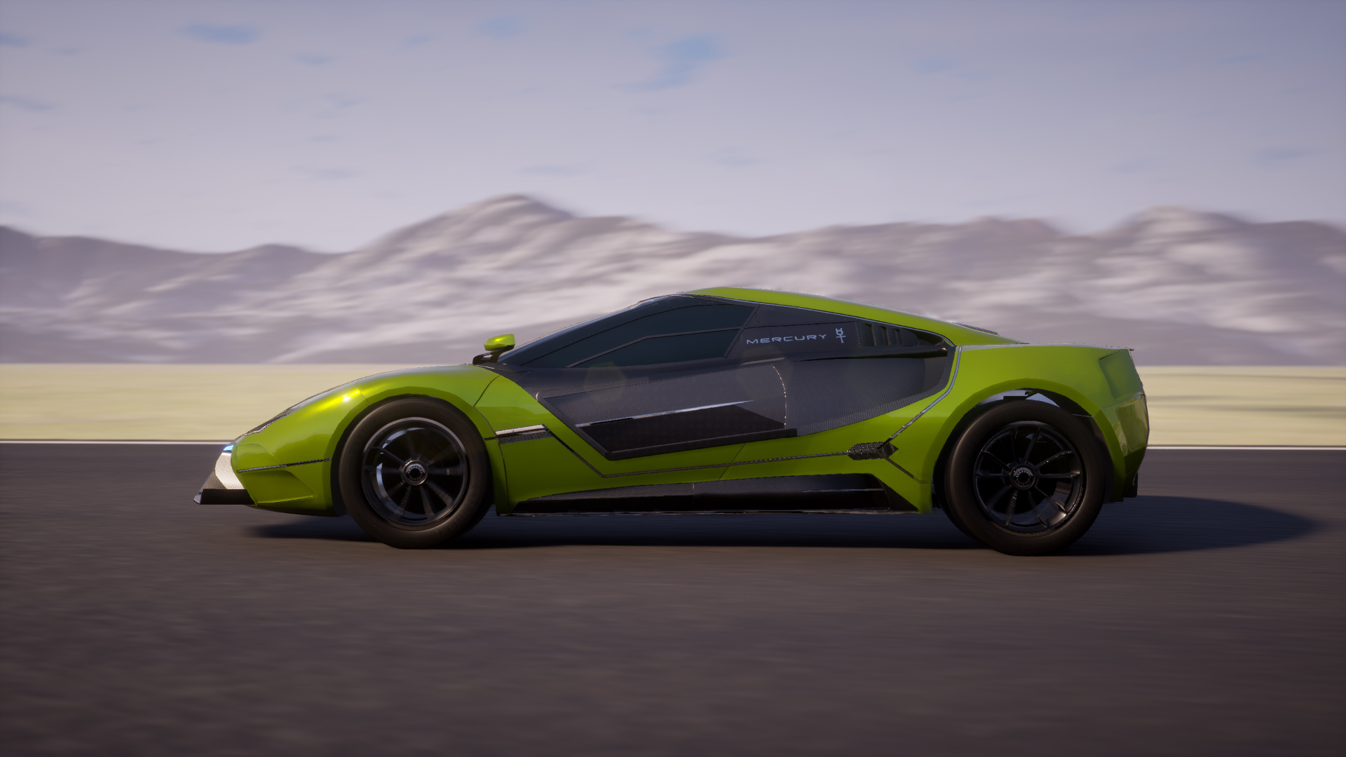
I am now very close to declaring the remake of the 2015 Mercury complete (at least in Automation). So here it is in a colour close to the original eye-searing lemon-lime of the Kee version ![]()
First, the overall idea of the shape:
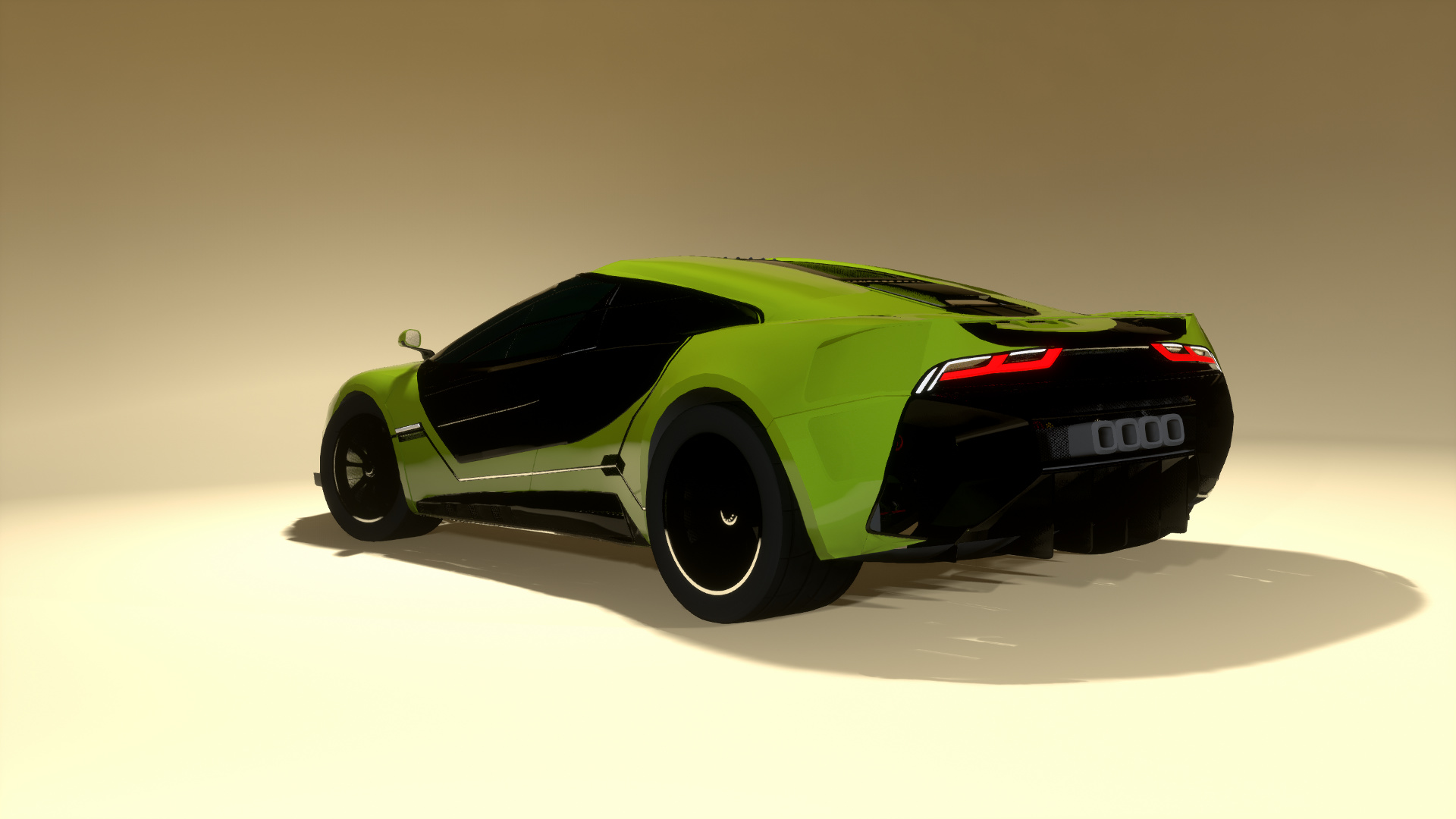

In more real-world lighting:

In which I unwittingly reveal that I am an ass man.

You’re probably thinking that rear window is a bit pointless and you’re mostly right. The rearward visibility in this thing’s gotta be a joke.
Many manly tears of frustration were shed in trying to reshape the A pillars into a panoramic window with a tapered roofline. The window-roof seam on this body is BRUTAL.

I do like that Chickenbiscuit’s lights glow in photo mode. I’m thinking I’ll make a fully cyberpunk trim but I just haven’t figured out the colours yet.
Okay last one for now.
I suppose that the next part is to go to town on .jbeam editing, during which Fite Me 3 will start happening, and then all that follows…
EDIT: here’s a video of a simple test, having fixed some things (and not others)
")
34 Likes
Considering the limitations of the 12C body, you have done an excellent job in remastering Mercury for UE4, right down to the exterior color, and added a few new styling features to boot. Well done!
So I may have mentioned to some people that with (a lot of) help (thanks to @ElMenduko for getting this ball rolling) I am trying to get the active aero working on the hypercars so that cars submitted for Fite Me 3 with active aero will… actually get something of the sort.
Right now however I have a bit of a technical issue. Beam doesn’t like making bodies that withstand stupid high forces such as what would be required to have a wing open at 450km/h and above.

The teal beam is the “hydro” that expands to lift the wing. However because I // several rows to leave that free, now the force is all concentrated on a “hinge” and this hinge, as you can see, is collapsing at high speeds which then causes the car to become very unstable.
Having already set the strength, spring and deform of the rear chassis to astronomical levels, I’ve spent like the last 3 hours on and off trying to find the appropriate geometry to fix this but all I seem to be doing is breaking the car and the simulation ![]()
So yeah it may be a bit more work getting this active aero up and running. I haven’t even started tuning the thing so that it’s actually functional.
EDIT: For reference, here’s the vanilla SBR with the active wing.
Closed, stationary:

Open partway at about 23m/s:

Airbrake deployed on hard braking:

It’s hard to see but the hydro beam is set between the sp3 and t4 nodes. For that matter the sp3 nodes are collision-less nodes whose sole purpose is to serve as the anchor point for the hydros. Looking at the rear wing file, it’s clear there’s a significant amount of reinforcement in addition to the frame, so I may try to emulate this too.
EDIT 2:

Well, I copied the SBR idea but clearly I’ve messed something up as the mesh is all kinds of turbofucked… but hey, now the car behaviour is as stable as it was before again (see the speed indicator)!
EDIT 3: worked out the problem, I placed the hydro anchor nodes in the group that goes with the car body and that has selfCollision and collision set to true by default, and kept overriding my own settings until I altered the argument of each node to take them out of the group as in:
//wing hydro anchor points
{"nodeWeight":0.5},
["HydroAnchorRL", 0.362788, 2.09, 1.48 { "group":"No_Group", "collision":false, "selfCollision":false }],
["HydroAnchorRR", -0.362788, 2.09, 1.48 { "group":"No_Group", "collision":false, "selfCollision":false }],
But the wing now collapses as usual at speed even with beamspring values of 2 million so time to go build a cage to try and steady it out…
11 Likes
I have to admire your dedication. Just looks to damn hard for mortals to mess with.
Alright, some progress! With the help of @TrackpadUser the collapsing beam problem has been sorted out. With that I learnt how to adjust the beams up front too.

Wing beams marked in Red

A bit hard to see here but reinforcement beams in yellow, and Hydro beams in cyan
With some study of how .lua and the electrics Streams work, I’ve managed to make some kind of active aero with independent front and rear flaps function more or less.
In the case of Mercury I had to actually test the behaviour of the car quite a bit as the relationship between traction and downforce changes markedly at around 240km/h, then at 320km/h, and especially between 400-450km/h where tyre traction in general goes extremely wonky…

A draft bit of logical arguments… my math and coding isn’t good enough to map out a set of values automatically so manual adjustments it is
In short, at 2130hp unless I mitigate how much front aero robs downforce from the rear, prodding the throttle will result in a spin at almost any speed, so I made it such that the further you depress the the throttle, the less the front wing activates. Right now though, this is causing problems if the car dips below 400km/h off throttle as suddenly the front wing goes from “closed” to “quite a bit open” and the car spins. I’ll have to work it out. Maybe I’ll slow the front hydros down, that will probably help a fair bit.
The only two things I haven’t worked out are:
- How to add my custom inputmap DRS button into the mix
- How to read the floating inputsteering value such that I can make the DRS cancel itself if the steering wheel is turned more than a few degrees (the wisdom of which I am debating, since this may in itself cause the car to suddenly destabilise). On that note if I work out inputsteering, then I can work out how to get 4 way aero working, which would be well wicked!
Work gradually continues.
EDIT:
because I’m one of the furthest things from an engineer you could get a physician with a humanities bent I stupidly forgot that the entire purpose of having .lua script is so you can put math in it.
So to smooth out the operation of the wing and make it truly adaptive, since this car’s stupid 2130hp means the behaviour is highly dependent on throttle input at varying speeds. Which means that what I should be doing is modelling the front wing angle as a function of the throttle.
Obviously this:
isn’t going to be it, but I’ve verified that it works
look how it accelerates like a bad motherfucker lmao
EDIT 2: the steering input works!

So in short, electrics.values.steering measures the steering angle. I’m not certain that this is in degrees of lock and I’m still too much of a noob at Beam’s UI to check this value in the console (anyone tell me how to do this I’d appreciate it). math.abs is the absolute value, as steering left produces a positive value, and right a negative one.
This is exactly what I want to know when, in future, I’ll be working on 4 way independent aero. This means things like the Mitsubishi HSR, or the Pagani Huayra, or even the SRT Tomahawk X (for that I’ll need some mad slidenodes), or even the Zenvo TSR-S’s silly pivot wing (for this I’ll need perfect placement of the hydros).
For this first project though, all I want is for the steering angle and the throttle to affect the front wing. I’ve decided the rear wing angle will remain fixed except when DRS is activated. Under most conditions, this car really needs all the rear downforce it can get. The front wing however, is such that the wing should exert more downforce with more steering lock (to an extent), and less if the throttle is depressed. This is because the car has more than enough power to power oversteer at almost any speed (all the way up to 500km/h).
But with the wing being what it is, above 400km/h if it is up at the maximum angle below stall angle (about 15 degrees), then it will also have a tendency to oversteer. Furthermore the rear wheels lose quite a bit of grip at these speeds, making keeping it stable under acceleration harder.
To combat this, I need something like this:

Where the x-axis is speed in km/h, the y-axis is wing angle in degrees, the red line is the maximum angle of the wing and the blue line is the minimum (except when DRS conditions are met and the toggle is pressed such that values.electrics.DRS = 1 or something).
To this end a suggestion from @ramthecowy later, and I might have something like this:

Where that e-x function may turn out to be something like this:


because electrics.values.wheelspeed is measured in m/s.
More testing to follow this week.
28 Likes
Ok enough editing one post. Here’s the next step of progress:

-
So that lovely exponential power formula didn’t work out because Beam took one sniff of using a floating value as an exponent and told me to fuck off lmao. So I had to use something a bit more discrete. Sad.EDIT: HA I got it to work! -
Rear wing currently just set to maximum effective angle above 80km/h when not braking. I am considering changing this to be more dynamic such that when not accelerating the wing is slightly lower. I don’t know whether I’ll change it for steering angle yet.
-
Front wing is quite dynamic but I need to build in a gradated throttle deadzone to reflect that the car requires more power to maintain a static velocity.
-
And of course, the DRS logic, which scares me right now so I haven’t tried it yet and probably won’t until like, Friday.
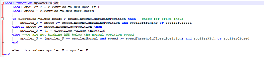
Okay I think I’m happy with this bit of logic for the front wing.

I didn’t show the full program or the other local values but you can probably extrapolate well enough. I think I will reduce the angle on the rear wing just slightly and only when the throttle is lifted off and the steering is relatively straight, just to reduce drag. So the calculations for its effect will be fairly simple.
But DRS will reduce the wing angles and shut the front wing for the purpose of absolute maximum acceleration. My mission will be to find out the minimum angle at which DRS can be activated and full throttle used without lighting the rear wheels up, which it definitely will haha. I may have to use an actual polynomial curve just to get over the stupid 400-450km/h traction loss.
20 Likes
How To Create Active Aero
an attempt at documentation
With thanks to @ElMenduko and @TrackpadUser for their help getting the process started
Now that I’ve figured out Mercury, more or less, I’ll see if I can take you through the process of making active aero from start to finish, because I have to start from scratch anyway due to some changes in my mesh and fixture designations.
1. Exporting and Unpacking
We start with the export, of course.
To make active aero work you should consider first the relationship between the wing angles in Automation and Beam. If you want your wing to be effect neutral when it is shut, make sure you set the Automation slider to 0. This is by far the easiest way as to fix it later requires cumbersome .jbeam edits that have no guarantee of working

This appears to have some superfluous bits! Wonder what I’m going to be doing with those…
Now to make editing faster so I can just open in Beam and reload the model with Ctrl + R, I’ll unpack the mod and put it in a folder named unpacked


2. Tidying up the Node labels so you can see what the hell you’re doing
Before you start this section, you should probably familiarise yourself with JBeams, Nodes, and Beams.
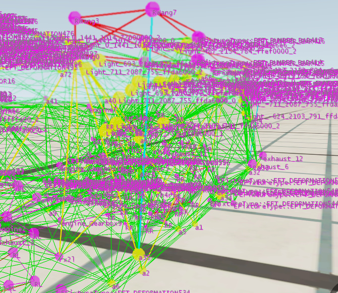
Now we load the mod in Beam, open the Debug menu, visualise the beams and nods and importantly, the node names.

Suffice to say it looks like a right mess right now. But it’s important to know which nodes are what as we’ll be doing a LOT of changing.
Okay let’s focus on the rear wing. I’ve now ascertained that the fixture is named EFixtureType::EFT_WING56

It shows up in the car’s .jbeam file as such:

That’s one hell of a mouthful. Let’s rename it RWang by finding and replacing every mention of it. The left part is the automation export designation. Don’t fiddle with that or the fixture will vanish. The stuff in [parentheses] is what you want to rename.
But note! that I did it such that I also renamed all the nodes in one fell swoop, because the nodes are what I need to rename, like so:


Much better.
3. Optimising the geometry and reinforcement of the wang wing
You will note there are 8 nodes in a box, and this comprises the frame of the wing. But a box isn’t exactly the sturdiest structure at high speed when there’s a lot of downforce on it. And I want to attach hydraulic beams to the back, so that has to be sturdy. So instead I am going to make it a wedge by deleting nodes RWang4 and RWang5

Now they are commented out I better also comment out all the beams they are supposed to anchor.

And while I’m at it I also highlighted the beams so I can visualise what I’m doing better. Red is the wing itself, yellow are all the beams that support the wing.

As you can see the supports for the wing are arranged around the mesh because that’s how it exports.
But this is a ticket to the mesh collapsing at speed, especially when I start removing supports because what I want to do next is to actually create a hinge by having the wing attached at only two points. Which means removing the beams that connect to RWang2, RWang3, RWang7 & RWang8.

Now it can swing around freely! (It would rather, if the fixtures I used to create a “mount” for it were set to collision = false, but they’re not for now).
As I said before, there is no reinforcement for the wing hinge. It needs some. We should attach it to the “subframe” of the car for maximum rigidity without actually messing up the mesh with too much tension. So I attached it to the nodes that actually frame the engine: rx1 and rx2 as well as body mesh nodes a2

At this point definitely reload your car again to make sure the physics don’t instantly wig out due to some beams snapping at the speed of light or something.
4. Installing the Hydraulics
Hydraulic beams are called hydros in Beam. You can read up on them here.
In short, a typical hydro .jbeam code will look like this:

- Ignore the
highlightbit, that’s just me colouring this cyan so you can see it when I’m done -
beamPrecompressionis the length the beam will immediately try to emulate on spawn. I have not yet been able to think of a reason to leave this at anything other than 1. If you want to play around with the other properties you should look them up first. - The bottom two lines are the important bit. They’re the hydro beams themselves. The first two parameters are the nodes which the beam is attached to. The beams, therefore, look like this:
-
"inputSource":is the key to everything. I shall explain that in further detail later. - As for the rest of the ins and outs (literally), well, that should be pretty self-explanatory as it pertains to how much and how fast the beam extends and shortens. There’ll be an element of trial and error in that, because it will become quite clear that the wing’s effect on downforce depends on the Angle of Attack, which is affected by how extended this hydro is. And that is the absolute crux of translating an active wing into one that effectively modulates how your car handles, so let that sink in for a while.
Now that we have a wing that starts off shut, let’s just check the AoA in the aero debug section. Turn it on and set the car in motion:

Perfectly balanced as all things should be Good, this is what we want to see.
5. Checking the aero effect:
You’ll note that I put the hydros right down the bottom of the .jbeam. It doesn’t have to go there, but it sure makes things easier. At the very least they should go after all the nodes because you can’t have beams without nodes and Beam will get very confused if you screw the file up that badly.
But what else is down the bottom of the files? "Triangles".
At this point I suggest you look up “Collision Triangles” in Beam. In a nutshell, they are triangles defined by groups of 3 nodes. They form a surface, and this surface then has an effect on either drag, lift, or both, depending on the angle of incidence at which air strikes it (thus is the extremely simplistic Beam aero model, not that we need more than this currently).
Some of you are wondering why “wings” in an Automation export file are the only thing that exert downforce. That’s because they’re the only things currently that automatically generate “coltris”. You can check this for yourself at the bottom of the .jbeam. If the fixture doesn’t generate coltris, it’s not having an effect on lift. But the good news is, if a fixture has nodes, then you can create coltris yourself!

I’m going to be changing this entirely, in tune with the real top speed of the car among other things. But what’s really important here is the stallAngle. This is, quite simply, the stall angle of the coltri (you should look up stall angle). In a nutshell it’s the angle at which a surface stops affecting lift and drag sharply rises. For perfectly smooth surfaces it’s around 15 degrees, or just under 0.262 radians (the value I suggest you use for the stallAngle).
This will ensure that you then have a wing with predictable and somewhat realistic (within the bounds of the simulation) behaviour, and also reveals my goal of an active wing: make sure it creates enough effective downforce for whatever speed and throttle input it requires, but also allow it to extend enough that it creates significant drag to act as an air-brake under braking. All that will be borne through the .lua programming, which is… still further down the track.
Tune in tomorrow for the next part and I’ll show you how to map out the custom inputs and the .lua! Then I’ll show you what the bigger plan is for my extra fixtures uwu wats dis

Here’s a really important tip: you can move fixtures just like you can move nodes using x,y,z coordinates. x is the left-right axis, y is the front-back axis, and z is the bottom-top axis. If a fixture isn’t attaching right or scaling to your liking, if it isn’t automatically integrated into the mesh of the car you can alter it, which is exactly what I’ve done here. In short I’m going to animate these front flaps too, but they’re in a finnicky spot so I’ve deleted their coltris and I’m using a different hidden wing to generate the downforce, because I’m cheating lmao.
13 Likes